- Marine Power Equipment
- Marine Propulsion Equipment
- Marine Deck Equipment
- Marine Mooring Equipment
- Marine Anchoring Equipment
- Marine Outfitting Equipment
- Marine Life Saving Equipment
- Marine Fire Fighting Equipment
- Marine Electrical Equipment
- Communication Navigation Equip
- Marine Auxiliary Machinery
- Marine Pumps and Piping System
- Marine HVAC System
- Marine Special Equipment
- Marine Decorations
- Marine Hardware
- Boat and Yacht

ADD: 18F, No. 157, Zhongshan 3 Rd., Yuzhong district, Chongqing, China
Post code: 400015
Mob/Whatsapp: +86-13640513313
TEL/FAX: +86-23-86595013
Email: manager@bochimachinery.com
Fixed Fire Extinguishing System


Fixed fire extinguishing/suppression systems are commonly used to protect areas containing valuable or critical equipment such as data processing rooms, telecommunication switches, and process control rooms. Their main function is to quickly extinguish a developing fire and alert occupants before extensive damage occurs by filling the protected area with a gas or chemical extinguishing agent.
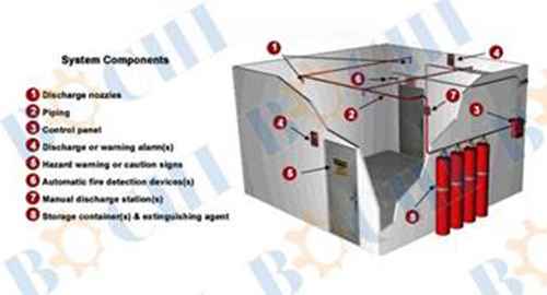
System Components
[In the image above, there is an cutaway 3-D image of a room with an entrance door and an exit door on the opposite wall, with two discharge nozzles, one on the wall between the doors, and one above the exit door (marked with an arrow and a number
1). Piping (marked with an arrow and a number
2) extends across the top of the room to the opposite wall with a set of four agent containers on the outer side of the wall attached to a control panel (marked with an arrow and a number
3). Outside the room at the entrance door is a control panel (marked with an arrow and a number
4) and on the door, there is a hazard warning sign (marked with an arrow and a number
5). Above the exit door inside the room, there is a fire detector mounted adjacent to the exit sign (marked with an arrow and a number
6). To the right of the exit door is a manual discharge station (marked with an arrow and a number
7). Outside the room, on the outer wall are the four agent storage containers connected to the piping (marked with an arrow and a number
8).When your mouse moves over each marked number in the 3-D image on the right, the component will be displayed to the left:
1. Discharge Nozzle [Rollover image includes image of discharge nozzle] Discharge nozzles are used to disperse the extinguishing agent into the protected area.
2. Piping [Rollover image includes image of piping with arrows] The piping system is used to transport the extinguishing agent (carbon dioxide, halon, argon, etc) from its storage container to the discharge nozzle.
3. Control Panel [Rollover image includes image of control panel] The control panel integrates all devices and displays their operational status and condition.
4. Warning Alarm [Rollover image includes image of fire alarm] Electronic devices that provide an audible or visual alarm when detected.
5. Warning and Caution Signs [Rollover image includes image of Caution sign and Halon Dump sign with text "Alarm will sound"] Hazard warning signs must be posted at the entrance to, and inside, areas protected by fixed extinguishing systems.
6. Fire Detectors [Rollover image includes image of fire detector] A device that detects fire and causes an alarm signal to be generated.
7. Pull Station [Rollover image includes image of pull station with pull pin and text "Pull pin then pull handle hard" and "Will release extinguishing agent"] A device that provides a way to manually discharge the fire extinguishing system.
8. Agent Storage Containers [Rollover image includes image of five agent containers] The storage system discharges agent into the piping and through the discharge nozzles when activated by a manual or automatic device.

 English
 Español